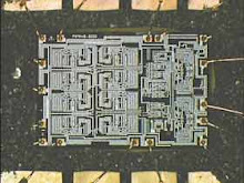
Friday 31 July 2009

Bootlegs #5 and #6

Another couple of variations have popped up on my travels.

Bootleg #5 (Thanks to Corn for the pic)

First is what i will call Boootleg #5. Another nice JAMMA looking single board design VERY similar to #4 but with enough small changes to warrant its own pic.

Small things such as the pair of unpopulated GFX roms and an IC missing where the "10" column marker is on the #4 bootlegs silkscreen are some. Those are just changes to the population of the parts that the bootleggers tweak along the process but they also made some minor board changes as can be seen by the larger power traces that run up where the A-T row marker silkscreen is on #4.


Bootleg #6 (Pic from presumably a won auction. By Cauterise / Arcadeotaku)

Another double board boot, space for but missing (as usual) the PS4. Looks to have a 56 way edge connector but has also been coverted TO JAMMA ?. Maybe earlier bootlegs didnt conform to the JAMMA standard ?


Friday 17 July 2009

Bootleg #4

Found another type of bootleg, I will lable this one as Bootleg #4

Bootleg #4

Quite a nice single board type but no attempt to provision for the PS4.


Pretty easy to see where the boards would be split, straight down the second column of silk screened row markers.

Friday 10 July 2009

PS4 Sum Error

The PS4 Microcontroller on a Bubble Bobble board turned out after eventually being decapped by the MAME team , to be a Motorola MC6803u4.

Its datasheet can be downloaded here for anyone who might be interested:

http://www.megaupload.com/?d=1S5VE22C

A suitable disassembler and corresponding assembler which can be used to work with the MCU can also be found here:

http://www.techedge.com.au/utils/dhc11.htm

An easy way to start experimenting is to use the MAME emulator that supports the dumped MCU. If you extract the bublbobl romset into a corresponding folder within your ROM folder, you can make modifications to the a78-01.17 file.

This brings us to our first hurdle. Any attempt to modify the stock binary dump and you will be greeted with the following screen on attempting to start the game.


Ah! A cheeky checksum is afoot.

Peeking at the disassembly, we find the following snippet which is called early on in the flow of the code.


A couple of pointers to this code.

The ROM in a 6803u4 resides from $F000-$FFFF.
The routine at LF1DB is one that writes to the shared Z80 RAM on the BB PCB. The byte to write is stored in the B accumulator, the address is in the indeX register.

What the routine does is set the index register to point to the start of the ROM and clears the A and B accumulators ready for use. It adds 2 bytes of the ROM to the double byte accumulator D (which in essence is just the pair of A and B accumulators) and increases the index register by 2, then loops. Once the entire ROM has been added up , the 2 calculated values are written to consecutive locations in the shared RAM. These locations are checked by the main Bubble Bobble program code, if they are not both $00 then we get the error screen.

An easy fix to this from our point of view is to just NOP out the "addD 0, X". The D accumulator never gets changed after its initial clearing and will therefore always equal $0000 after the loop.

Give it a try if you feel like it. Change the date in the text string towards the end of the binary to simulate the error. Then if you NOP out the command by changing the 2 bytes at offset $27F from E300 to 0101 it should then run fine.

Saturday 4 July 2009

Differing types of PCB

I guess a good start might be to identify the different types of PCB (both original and bootleg). So here goes.

Original PCB (Thanks to Tormod Tjaberg for the pic)


Notice the original PS4 with the Bub silkscreen on it, a sure fire way to identify original boards.

Bootleg #1 (Thanks to Invzim for the pic)


( Not sure why but Blogger keeps rotating the picture :( )


Has a JAMMA compatible pinout.

Blank space for the PS4. According to Invzim (the owner of this PCB) although it has a space designated for the MCU, the majority of the pins are NOT connected.


Bootleg #2 (Thanks to JROK for the pic)


Pinout looks identical to the original Taito. Is missing the seperate power connector though.

Space for the PS4. Looks as thought the entire PCB is a full copy of the original.

Bootleg #3


Can anyone help with this one , apparently there is a version which has a 68705 MCU onboard ?